

GPRS /4G Water Meter Instruction Manual
Categories:
Remote Water Meter
Email:info@xintaimeter.com


GPRS /4G Water Meter Instruction Manual
Categories:
Remote Water Meter
Email:XintaiValve@163.com
Product introduction
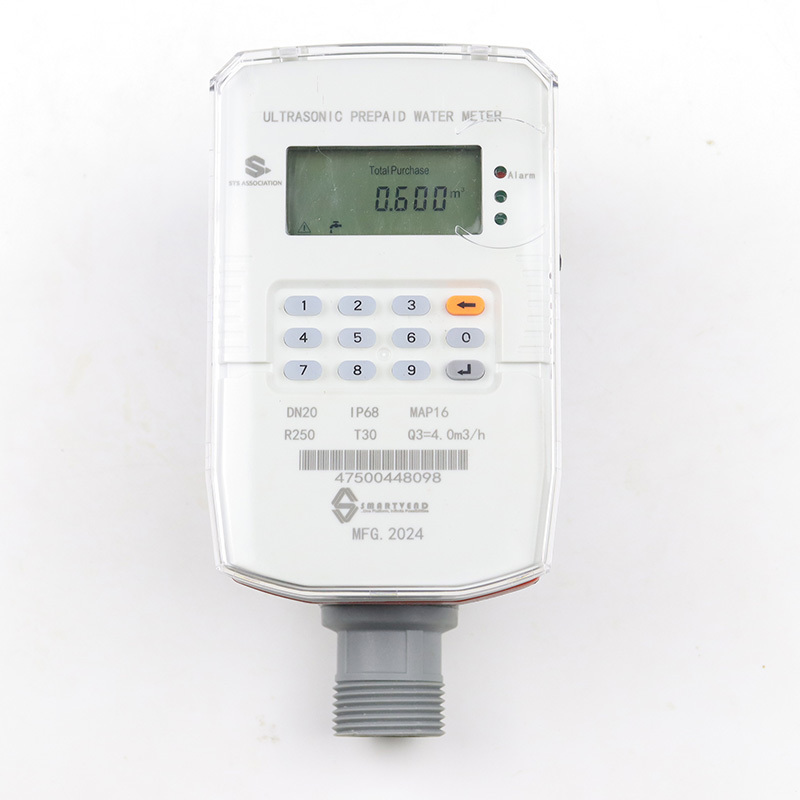
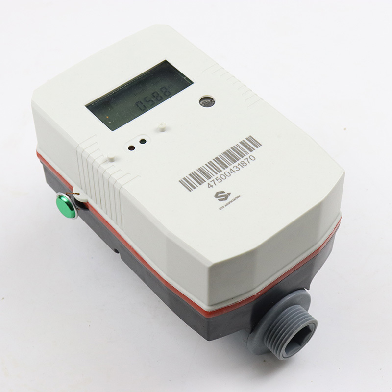
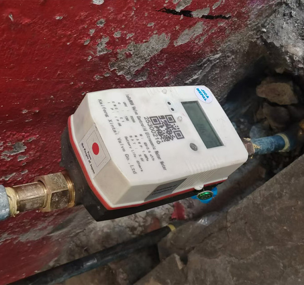
The LXS-15~50 series small-diameter GPRS /4G wireless remote water meter is a smart meter developed to facilitate wireless remote meter reading based on the actual needs of intelligent management of water supply companies. It adopts a split design, and the electronic unit is installed in an independent fully sealed cavity. The waterproof performance reaches IP68 level. It does not change the structure of the traditional wet or dry water meter, and does not affect the measurement accuracy and sensitivity. It communicates with the GPRS /4G module through the GPRS /4G module. The main station communication uploads data to the main station, realizing the functions of fully automatic remote reading of water meter data and data sharing with the settlement center.
Technical Parameters
1. Electronic performance parameters
| Items | Parameters | Marks |
| Operating Voltage | DC3.6V | Lithium battery powered |
| Operating temperature | -20—100℃ | Operating temperature of electronic modules |
| Working humidity | 10%-90% Relative humidity, no condensation | |
| Working frequency |
GPRS: GSM850MHz;EGSM900MHz;DCS1800MHz;PCS1900MHz; 4G:LTE-FDD Band 1/Band 3/Band 5/Band 8 ▪ LTE-TDD Band 34/Band 38/Band 39/Band 40/Band 41 |
|
| Upload time | You can set the upload interval in hours from 1 to 255 hours. | The default interval is 24 hours, that is, uploading once a day |
| Battery life | ≥8 years | |
2. Flow technical parameters
| Items | Parameter | ||
| Nominal caliber | DN15 | DN20 | DN25 |
| Range Ratio | R100 | ||
| Q4(m³/h) | 3.125 | 5 | 7.875 |
| Q3(m³/h) | 2.5 | 4 | 6.3 |
| Q2(m³/h) | 0.04 | 0.064 | 0.1008 |
| Q1(m³/h) | 0.025 | 0.04 | 0.063 |
| Temperature Class | T30/T50/T90 | ||
Indication error: Within the water temperature range of 0.1℃ to 50℃, the maximum allowable error of the water meter is ±2% in the high area (Q2≤Q≤Q4) and (±5%) in the low area (Q1≤Q<Q2).
Appearance and specifications
| Caliber | L | W | H2 | Thread Connection Pipe ϕ | Thread Connection Case ϕ |
| DN15 | 165 | 90 | 150 | R 1/2 | G 3/4 B |
| DN20 | 195 | 90 | 152 | R 3/4 | G 1 B |
| DN25 | 225 | 104 | 175 | R 1 | G1 1/4 B |
Wireless remote water meter specifications and dimensions table
Magnetic field induction intensity
Magnetoresistive switch:
| Symbol | Min | Type | Max | Unit |
| Bop,Ta=25℃ | ±17 | ±37 | ±55 | Gs |
| Brp,Ta=25℃ | ±10 | ±25 | ±40 | Gs |
| Bhyst,Ta=25℃ | 3 | 12 | 18 | Gs |
Reed Pipe:
| Serial number | Items | Unit | Numerical value |
| 1 | Electric shock form | 1C SPST-NC | |
| 2 | Electric shock material | Ru | |
| 3 | Electric shock load | W | 5 |
| 4 | Maximum switching voltage | V(DC/AC) | 175/125 |
| 5 | Maximum switching current | mA | DC400/AC280 |
| 6 | Maximum contact resistance | MΩ | 120 |
| 7 | Minimum insulation resistance | Ω | 10.6 |
| 8 | Sensitivity value | AT | 10-20 |
| 9 | Contact capacitance | PF | 0.8 |
| 10 | Working temperature | ℃ | -55~120 |
Installation, use and maintenance methods
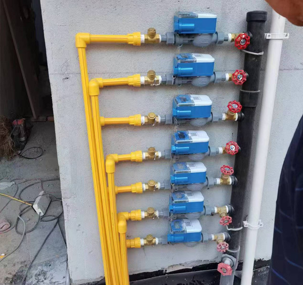
1. A wireless remote water meter of appropriate caliber should be selected based on the pipe diameter and water consumption at the installation location.
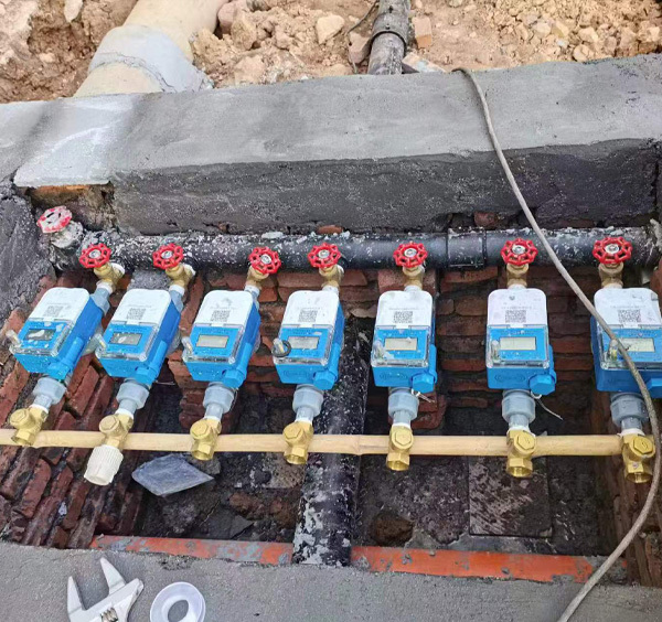
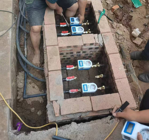
2. The installation location should avoid exposure, freezing, pollution, moisture and flooding to facilitate disassembly and meter reading. During the freezing period, in addition to wrapping the water meter and water pipes, close the inlet valve of the water meter and open the outlet valve and faucet when not in use. This can prevent the water meter from being damaged due to freezing expansion. It is recommended to install it in a special water meter box.
3. The water meter should be installed horizontally, with the letter facing up and the arrow direction in the same direction as the water flow.
4. It is necessary to wash away the gravel, sediment and other debris in the newly installed pipes before installing the water meter to avoid causing water meter failure.
5. For accurate measurement, the faucet should be higher than the water meter.
6. If the water meter is installed at the boiler water inlet pipe, prevent the backflow of hot water from scalding the water meter.
7. The water meter should not be directly connected to the pipeline. The water meter and the pipeline should be connected through pipes, sealing washers, and connecting nuts. When disassembling the water meter, do not use hard plates to avoid twisting the case.
8. The water meter should be protected from excessive stress caused by pipes and fittings. If necessary, the water meter should be installed on a base or bracket.
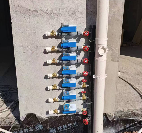
9. Valves should be installed before and after the water meter to facilitate maintenance and replacement.
10. Do not install the water meter in a metal water meter box to avoid signal shielding and preventing remote meter reading.
Key words:
Related Products
Product line
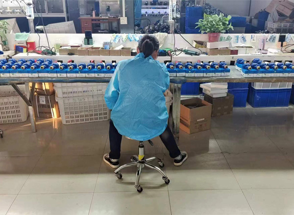
Project Cases
Leave a message
Leave your contact information and we will contact you during business hours


